Project overview
The raytracer handles four primitives (spheres, boxes, cylinders, and triangle meshes), material properties through BRDF definitions, and texture mapping. Ray-shape intersections go through a Bounding Volume Hierarchy (BVH) instead of a loop over every shape in the scene.
Intersection calculation verification
Purpose
Check that intersection detection and nearest-hit selection are correct: that the closest intersection point (minimum t value) is the one returned, and that all valid intersections are considered before the frontmost one is picked.
Implementation
Each shape type (Sphere, Box, Cylinder, Triangle) has its own intersection algorithm. The scene is rendered with each pixel colored by the intersected object’s material diffuse color (the Kd component).
Verification method
Each primitive comes out in its assigned material color:
- Spheres appear in their assigned Kd color
- Boxes appear with their own distinct material properties
- Cylinders and mesh triangles appear in their respective colors
- Regions where no intersection occurs appear black (there are none in this scene)
Interpretation
A correct image means that:
- Ray generation from camera coordinates is accurate
- Each primitive’s intersection test identifies its hit points
- Material assignment to shapes survives the intersection process
- Object boundaries fall where the intersection algorithms put them
Test images
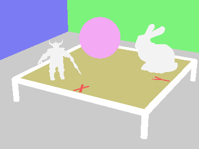
[Diffuse]
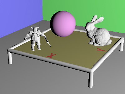
[Diffuse + Normal]
Ray parameter (t) verification
Purpose
Check that the ray parameter t (the distance along the ray direction) is correct at each intersection.
Implementation
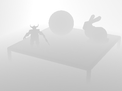
In raytrace.cpp the distance is drawn as normalized grayscale, with maxDistance set to 10.0 for the scene scale:
float maxDistance = 10.0f;  // scene scale
float normalizedT = std::min(1.0f, closest.t / maxDistance);
color = Color(normalizedT, normalizedT, normalizedT);
Verification method
- Objects closer to the camera appear darker, since a smaller t gives a lower pixel intensity
- Objects farther from the camera appear brighter, since a larger t gives a higher intensity
- Gradual grayscale transitions across object surfaces confirm continuous t calculation
- Shadow boundaries and occluded regions show the expected depth relationships
Interpretation
A correct t-value image means:
- Ray direction vectors are normalized
- The parametric ray equation
P(t) = origin + t * directionis evaluated correctly - Closest intersection filtering (
closest.t < INF) selects the nearest hits - Depth relationships between objects are geometrically accurate
Test image
Surface normal verification
Purpose
Check that surface normals at intersection points are calculated correctly.
Implementation
The shading is replaced by the normal itself, in raytrace.cpp (line 235):
// Display normal as color
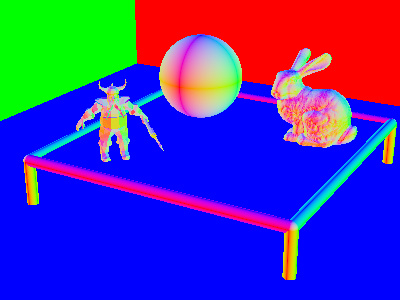
color = glm::abs(closest.normal);
Each component of the normal vector becomes an RGB channel, with absolute values so the colors stay positive.
Verification method
- Sphere normals: radiate outward from the center, which gives symmetric gradient patterns
- Box normals: perpendicular to each face, so 3 distinct normal directions show
- Cylinder normals: vary smoothly around the curved surface, constant on the end caps
- Mesh triangles: normals per face, or interpolated across vertices for smooth shading
Interpretation
A correct normal image confirms:
- Each primitive’s geometric normal calculation is accurate
- Normal vectors point outward from the surface
- Normals are normalized to unit length
- For meshes, vertex normal interpolation produces smooth shading
- Lighting calculations built on them will be geometrically valid
Test image
Bounding box hierarchy validation
Purpose
Check the bounding box hierarchy and the ray-box intersection by rendering the scene geometry at bounding box level instead of at shape level, and confirm that each bounding box (AABB) encloses the geometry inside it.
Implementation overview
The bounding box extends the one from the BVH v2 library (bvh::v2::Bvh:BBox), in bbox.h. Each SimpleBox wraps the library’s bounding box and extends it with individual vertices or with other bounding boxes, which keeps the bounds tight around the geometry.
The bounding box intersection is the same for every shape, so the logic lives in shape.h, the parent class of all of them.
The shape intersection is replaced with the bounding box intersection in acceleration.cpp (line 45):
// Render scene at bounding box level instead of actual shapes
auto result = shape->intersectBoundingBox(ray);
Instead of calling shape->intersect(ray), which traces rays against the actual geometry, this returns intersection data from the axis-aligned bounding box (AABB) that encloses each shape. The intersection point, normal, and the other properties come from the box surface rather than from the primitive.
Verification method
- Box normals: 3 distinct normal directions, perpendicular to each of the 6 faces
- Layered boxes: multiple overlapping boxes become visible, which is the acceleration hierarchy
- Ray coverage: all rays that intersect actual shapes also intersect their bounding boxes (superset verification)
Interpretation
A correct bounding box image confirms:
- Bounding box calculations enclose all the geometry within each shape
- Box-ray intersection tests are geometrically valid
- BVH acceleration structure bounds are computed correctly
Test images
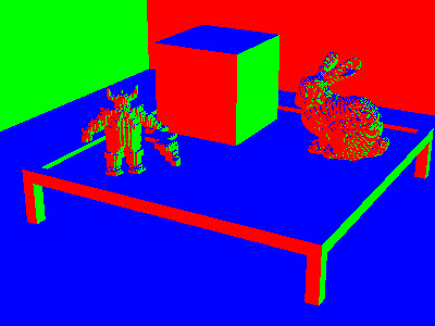
[Normal]
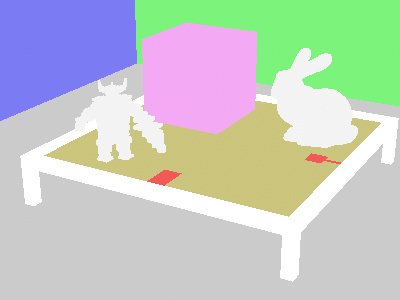
[Diffuse ]
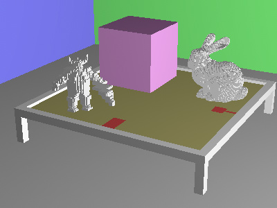
[Diffuse + Normal]
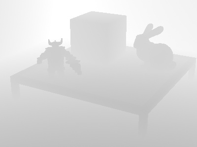
[T-Value]
Spatial data structure performance verification
Purpose
Measure how much the BVH acceleration structure speeds up a render.
Implementation overview
The raytracer uses the BVH v2 library (bvh::v2::Bvh) with axis-aligned bounding boxes. Every shape is wrapped in a BvhShape, and those are loaded onto the BVH builder. Two builders were timed: MiniTreeBuilder (multi threaded) and SweepSahBuilder (single threaded).
Performance measurement
traceImage is wrapped in a timing function measureTimeMs, which measures how long the call takes and prints it at the end (main.cpp line 126):
  double renderTime = measureTimeMs([&]() {
      // RayTrace the image
      scene->TraceImage(image, 1);
  });
Speedup analysis
Simple objects scene
Run timing with only basic primitives (few spheres/boxes):
- Result: minimal speedup
- Reason: BVH construction and traversal overhead dominates with few objects
- Trade-off: the acceleration structure’s overhead exceeds the benefit of culling
Complex scene
Run with Dwarf model:
- Expected speedup: somewhat observable
- Performance gain: the BVH reduces intersection tests per ray, especially with the dwarf model
Run with Dwarf and Stanford Bunny:
- Expected speedup: significant speedup observed (approx 119%)
- Performance gain: the BVH cuts the intersection tests per ray sharply
- Scalability: speedup increases proportionally with object count
Measurements
| Method | Trial 1 | Trial 2 | Trial 3 | Builder Type |
|---|---|---|---|---|
| Non-BVH | 89423.45 ms | 89623.23 ms | 89784.13 ms | N/A |
| SweepSahBuilder | 130.44ms | 132.91ms | 136.96ms | SAH optimization |
| MiniTreeBuilder | 111.41ms | 109.23ms | 110.55ms | ThreadPool-optimized |
Overall the BVH gives approx. 200% improvement over the non-BVH implementation, and MiniTreeBuilder renders ~18% faster than SweepSahBuilder (130-137ms) at similar quality.
Code implementation
The Scene::Finit() function initializes the acceleration structure:
void Scene::Finit() { this->accelStruc = new AccelerationBvh(this->shapes); }AccelerationBvh (lines 78-93) sets up the builders used for the BVH, and TraceImage uses accelStruc to compute the intersection record for each ray.
Interpretation
- For simple scenes: the BVH overhead may exceed the benefit; consider disabling it for minimal geometry
- For complex meshes (bunny, dragon, etc.), the speedup confirms the BVH is worth its overhead
- Acceleration structure: scene space is partitioned using bounding boxes
- Ray traversal: the BVH identifies the relevant primitives
- Performance improvement: validates the spatial data structure implementation
- Scalability: O(log n) behavior rather than the naive O(n) approach
Summary
The raytracer:
- Computes accurate ray-primitive intersections with correct geometry
- Calculates correct t-values representing distances along rays in world space
- Generates accurate surface normals for lighting calculations
- Implements acceleration structures for the complex scenes that need them
Class structure
Core geometry and intersection
Ray
A 3D ray with an origin and a normalized direction vector. evaluate(t) returns the point along the ray at parameter distance t.
Intersection
The data for one ray-shape intersection: hit distance t, intersection position, surface normal, and a reference to the intersected shape. Has a distance getter for the hit parameter.
Interval
An interval along a ray, with minimum and maximum t-values and their associated normals. Used internally for slab-based intersection testing in boxes and cylinders.
Geometric primitives
Shape
Abstract base class for all geometric primitives in the scene. Defines the interface for ray intersection, bounding box computation, and material association.
Sphere
A sphere defined by a center position and a radius. Solves the quadratic equation for the ray-sphere intersection and computes the surface normal from the hit.
Box
An axis-aligned bounding box (AABB) defined by a corner and a diagonal vector. Uses the slab intersection method for ray-box collision detection.
Cylinder
A cylinder with a base position, an axis direction, and a radius. Uses a coordinate transformation and interval testing to compute the ray-cylinder intersection.
Triangle
A triangular polygon defined by three vertices (v0, v1, v2). Uses the Möller-Trumbore algorithm for the ray-triangle intersection.
Material and texture system
Texture
Wraps image texture data loaded from a file path with the STB image library. Stores the image dimensions (width, height, depth) and the pixel data used for surface detail mapping.
Material
Base class for surface shading properties: diffuse (Kd), specular (Ks), and shininess (alpha) coefficients. Can optionally reference a texture, and identifies light-emitting materials.
BRDFMaterial
Extends Material with the BRDF (Bidirectional Reflectance Distribution Function) implementation. Inherits the diffuse, specular, and alpha properties for physically-based shading.
Light
A Material subclass for emissive surfaces, with the radiance value stored in Kd. Overrides isLight() to return true, so the renderer handles it as a light.
Camera system
Camera
Holds the camera position, orientation (quaternion), and frustum properties. Transforms normalized screen coordinates into world-space ray directions using the camera orientation.
Acceleration structures
SimpleBox
A bounding box wrapper extending the BVH library’s BBox<float, 3> with GLM vector compatibility. Has construction and extension methods for building the spatial structure.
BvhShape
Adapter class wrapping a Shape* pointer for the BVH library. Passes bounding box and intersection queries to the underlying Shape, converting between coordinate systems.
AccelerationBvh
Builds and traverses the BVH (Bounding Volume Hierarchy) for accelerated ray-scene intersection. Wraps all scene shapes and runs the closest-hit queries against the spatial partitioning.
Scene management
VertexData
Per-vertex geometry data: position, normal, texture coordinates, and tangent vector. Used by the mesh loading system for vertex attribute storage.
MeshData
Container for mesh geometry, with a vertex array and indexed triangle connectivity. Associates the mesh data with a material, so one set of surface properties applies across it.
Scene
Holds the complete ray-traced scene: camera, shapes, materials, lighting, and acceleration structure. Parses scene files, loads mesh data, and provides the TraceImage() interface for image generation.