Project overview
This project extends the microfacet BRDF renderer from Project 3 to support light transmission through surfaces. Project 3 established a full Cook-Torrance specular model (Phong NDF + Smith G + Schlick F) alongside a Lambertian diffuse term, but every path that struck a surface was assumed to either be absorbed or reflected, with no light passing through. Project 4 adds a third mode of light interaction: refraction, in which light crosses a surface boundary and changes direction according to Snell’s law, while its intensity decays with distance according to Beer’s law.
The three functions that form the BRDF interface (SampleBRDF, pdfBrdf, and EvalScattering) are each extended to handle a three-way choice between diffuse, reflection, and transmission, alongside two new material parameters: Kt (transmission color / Beer’s law coefficient) and ior (index of refraction). A helper, computeEta, centralizes the IOR bookkeeping that all three functions require.
Test scene
The test scene places transmissive glass objects alongside the reflective surfaces from previous projects. Colored glass objects demonstrate both refraction (bending of light paths) and Beer’s law absorption (tinted color deepening with path length through the medium), while the light and surrounding diffuse walls contribute to visible caustic-like patterns through the transparent geometry.
Material system extensions
Two new parameters are added to the Material struct in include/shape.h:
vec3  Kt;   // Transmission color: color of light after traveling one unit through the material
float ior;  // Index of refraction (1.0 = air, ~1.5 = glass)
The scene file parser in Command() is updated to accept brdf lines with either 7 parameters (original, no transmission) or 11 parameters (with Kt and ior):
if (f.size() == 8)
    currentMat = new Material(vec3(f[1],f[2],f[3]), vec3(f[4],f[5],f[6]), f[7]);
else
    currentMat = new Material(vec3(f[1],f[2],f[3]), vec3(f[4],f[5],f[6]), f[7],
                              vec3(f[8],f[9],f[10]), f[11]);
All previously defined scenes still load without modification.
Index of refraction: computeEta
A helper function centralizes IOR computation for all three BRDF interface functions:
std::pair<float,float> Scene::computeEta(vec3 outDir, vec3 N, Material* mat)
{
    float outDotN = glm::dot(outDir, N);
    if (outDotN > 0.0f) {
        return { 1.0f, mat->ior };   // path leaves object: air -> material
    } else {
        return { mat->ior, 1.0f };   // path enters object: material -> air
    }
}
By convention outDir (ωo) is the path direction toward the camera. When ωo·N > 0, the outgoing ray is on the same side as the surface normal, meaning the path is leaving the object, so ηi = 1 (air) and ηo = IOR. When ωo·N < 0, the path is entering the object, so ηi = IOR and ηo = 1. The ratio η = ηi / ηo is used throughout sampling, PDF, and evaluation.
BRDF sampling: SampleBRDF
The sampler now chooses between three strategies proportionally to the magnitudes of Kd, Ks, and Kt:
float s  = length(Kd) + length(Ks) + length(Kt);
float pd = length(Kd) / s;   // probability of diffuse
float ps = length(Ks) / s;   // probability of specular

if (e < pd)       → diffuse:      SampleLobe(N, sqrt(e1), e2)
if (e < pd + ps)  → reflection:   2(ωo·m)m − ωo
else              → transmission: refract or TIR
For diffuse, a cosine-weighted direction is drawn directly. For reflection, a microfacet normal m is sampled from the Phong NDF and the reflected direction is returned. For transmission, the same m is used but the ray is refracted through the surface using the Snell’s law formula:
// Sample transmission direction
float r = 1.0f - (eta*eta) * (1.0f - (outDotM * outDotM));

if (r < 0.0f) {
    // Total Internal Reflection: return reflection direction
    return 2.0f * dot(outDir, m) * m - outDir;
} else {
    int sign = dot(outDir, N) >= 0.0f ? 1 : -1;
    return (eta * outDotM - sign * sqrt(r)) * m - eta * outDir;
}
The radicand r = 1 − η²(1 − (ωo·m)²) detects total internal reflection (TIR): when it is negative, no real refracted direction exists and the sampler falls back to the reflected direction, conserving energy. Otherwise the full Snell’s-law refraction vector is returned.
BRDF PDF: pdfBrdf
The PDF is the weighted sum of all three directional PDFs:
P = pd·Pd + pr·Pr + pt·PtThe diffuse PDF is unchanged:
float Pd = max(0.0f, dot(L, N)) / PI;The specular reflection PDF uses the Phong NDF with the reflection half-vector m = normalize(L + V):
float Pr = (dm * dot(m, N)) / (4.0f * vDotM);The transmission PDF requires the refraction half-vector m = -normalize(ηo·L + ηi·V), which points into the surface rather than out. The radicand test distinguishes TIR from true refraction:
// TIR case: use reflection PDF
Pt = dm * dot(m, N) / (4.0f * |wi·m|);

// Refraction case:
float denom = (no * LDotM + ni * vDotM)²;
Pt = dm * dot(tm, N) * (no² * |wi·m|) / denom;
Beer’s law attenuation
When a path travels through a transmissive object it accumulates absorption. Kt is defined as the color of light remaining after traveling one unit through the medium. For a path that has traveled distance t, the attenuation is:
A(t) = exp(t · log(Kt))This is derived from Beer’s law: A(t) = e^{-ct} where c = -log(Kt).
In EvalScattering, the attenuation is computed only when the path is inside the object (i.e., ωo·N < 0, meaning it has just hit the inner surface):
vec3 atten = vec3(1.0f);
if (outDotN < 0.0f && t > 0.0f) {
    atten = glm::exp(t * glm::log(mat->Kt));
}
The t value is the intersection distance from the previous bounce, already stored in the Intersection struct. This attenuation factor multiplies the transmission term in both the TIR and refraction return cases, so that energy is always reduced when traveling through a medium regardless of whether TIR occurs.
Full BRDF evaluation: EvalScattering
EvalScattering accumulates all three terms, guarded by whether each lobe’s probability weight is non-zero:
vec3 diffuse     = (pd > 0) ? Kd / PI : vec3(0);
vec3 specular    = (pr > 0) ? D*G*F / (4 * |outDotN|) : vec3(0);
vec3 transmission = vec3(0);

if (pt > 0) {
    // Compute Beer's law attenuation A(t)
    // Compute refraction half-vector tm
    // Test radicand r

    if (r < 0) {   // TIR
        transmission = A(t) * D*G*F / (4 * |outDotN|);
    } else {       // Refraction
        transmission = A(t) * D*G*F_complement * |wi·m| * |wo·m| * no²
                       / (|wi·N| * |wo·N| * (no*(wi·m) + ni*(wo·m))²);
    }
}

return |N·wi| * (diffuse + specular) + transmission;
For the refraction case, F_complement = (1 - F) is the transmitted fraction of energy, the part that Fresnel says crosses the boundary rather than reflecting. The |wi·m|·|wo·m|·no² numerator and (no·(wi·m) + ni·(wo·m))² denominator terms are the standard microfacet transmission BTDF factors, which keeps the evaluation consistent with the PDF.
The specular and TIR terms use the same Cook-Torrance specular half-vector m = normalize(L + V), while the refraction term uses its own half-vector tm = -normalize(no·L + ni·V).
MIS weights: the power heuristic
Following the handout, MIS weights use the power heuristic w = p² / (p² + q²) rather than the balance heuristic p / (p + q) from Project 3. Both the explicit and implicit light connections compute the cross-strategy probability and apply the weight:
// Explicit light connection
float p_brdf = pdfBrdf(N, inDir, outDir, mat);
float weight = (p*p) / (p*p + p_brdf*p_brdf);
C += weight * W * (f / p) * L_radiance;

// Implicit light connection
float p_light = PdfLight(Q) / GeometryFactor(P, Q);
float weight  = (p_brdf*p_brdf) / (p_brdf*p_brdf + p_light*p_light);
C += W * weight * Q_radiance;
The power heuristic suppresses the low-probability strategy’s contribution more aggressively than the balance heuristic, which helps when one strategy dominates strongly, as it does for specular and transmissive lobes where the BRDF is concentrated in a narrow solid angle.
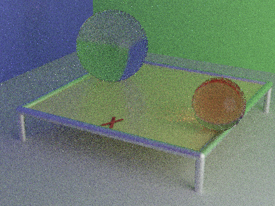
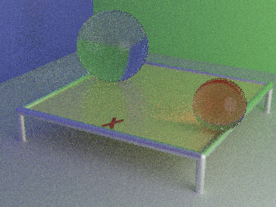
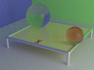
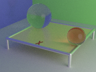
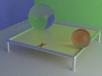
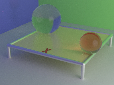
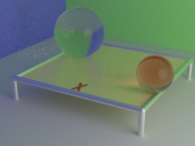
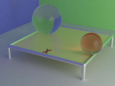
Comparison: no MIS vs. the power heuristic
| Passes | No MIS (Equal Weight) | Power Heuristic |
|---|---|---|
| 64 |
Click to zoom
 |
Click to zoom
 |
| 256 |
Click to zoom
 |
Click to zoom
 |
| 1024 |
Click to zoom
 |
Click to zoom
 |
| 4096 |
Click to zoom
 |
Click to zoom
 |
Ray offset for transmission
A transmitted ray that continues through the surface must not immediately hit that surface again. For reflected rays the origin is offset along +N; for transmitted rays it must be offset along −N (into the object). The offset direction comes from checking whether the sampled inDir points away from or through the surface:
bool isTransmission = dot(inDir, N) < 0.0f;
Ray Q(P.position + (isTransmission ? -1.0f : 1.0f) * EPSILON * N, inDir);
The extended path ray then does not re-intersect the surface it just departed from, whether the path is reflecting or refracting.
Test scenes
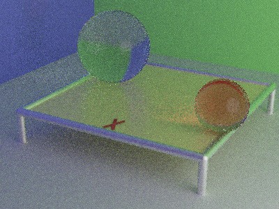
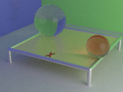
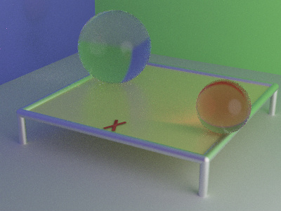
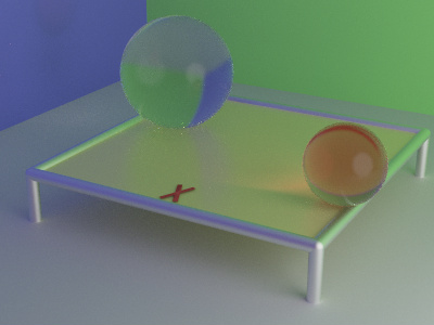
Each scene is rendered at pass counts growing from 64 to 4096, to show how the transmissive effects converge.
Scene 1: glass spheres on the reflective table
The primary test scene places two glass spheres on the reflective table surface from previous projects. The larger sphere uses a near-neutral glass material (Kt = (0.9, 0.9, 0.9), ior = 1.25), while the smaller sphere uses a red-tinted glass (Kt = (0.9, 0.1, 0.1), ior = 1.25) that heavily absorbs green and blue wavelengths, transmitting only red light. The overhead area light, colored walls, and reflective table surface from Project 3 are retained. The smaller red sphere is positioned in front of the larger neutral sphere; the refracted image of the scene visible through the red sphere is tinted red by Beer’s law absorption, while the neutral sphere produces an undistorted, colorless refraction of the background.
Test images
| 64 Passes | 256 Passes |
|---|---|
Click to zoom
 |
Click to zoom
 |
| 1024 Passes | 4096 Passes |
Click to zoom
 |
Click to zoom
 |
Scene 2: glass sphere and Stanford Bunny
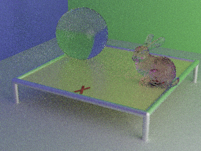
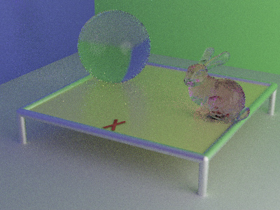
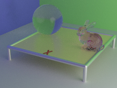
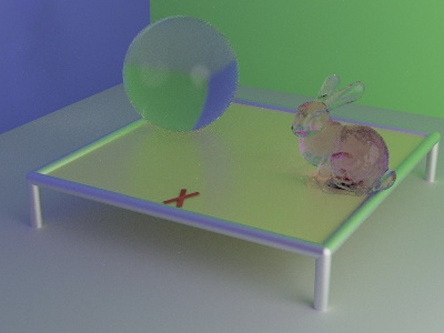
This scene introduces the Stanford Bunny as a transmissive object alongside a single glass sphere. The bunny uses a pink-tinted glass material with Kt = (0.9, 0.1, 0.9) and ior = 1.5, which absorbs green wavelengths more than red, producing a rose-colored tint that deepens through thicker regions of the mesh. The sphere uses a near-neutral glass (Kt = (0.9, 0.9, 0.9), ior = 1.25) for contrast. The non-convex geometry of the bunny exercises the transmission system: rays must correctly refract upon both entering and exiting the mesh, handle total internal reflection on tightly curved surfaces, and accumulate Beer’s law attenuation proportional to the chord length traveled through the interior.
The table surface and colored walls remain visible through the bunny’s body, with the pink tinting becoming more saturated in thick cross-sections such as the torso and haunches. The ears, being thin, transmit with minimal color shift. The neutral glass sphere alongside it is a reference, which separates the pink absorption from the refractive distortion.
Test images
| 64 Passes | 256 Passes |
|---|---|
Click to zoom
 |
Click to zoom
 |
| 1024 Passes | 4096 Passes |
Click to zoom
 |
Click to zoom
 |
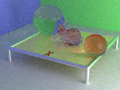
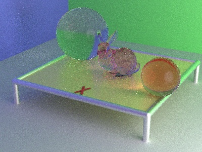
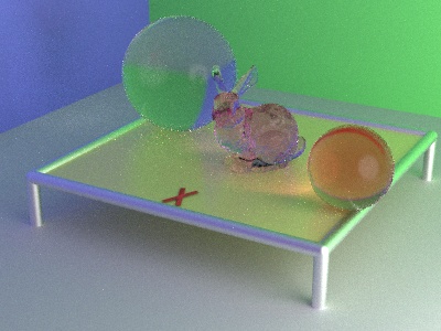
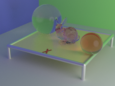
Scene 3: two glass spheres and Stanford Bunny
The final scene combines all three objects: the two glass spheres from Scene 1 (neutral and red-tinted) and the pink glass bunny from Scene 2. This tests several transmissive objects at once: inter-object refraction chains where a ray exits one glass surface and immediately enters another, compounded Beer’s law attenuation across successive media, and the increased path complexity that arises from three distinct IOR boundaries in a single scene.
The interaction between the objects produces the most visually complex refraction behavior of the three scenes: rays passing through the bunny’s right ear (one of its thinnest regions) reveal the larger neutral sphere positioned behind it, whose own refraction distorts the reflection of the colored side walls into a compressed, curved image visible through the bunny’s silhouette.
Test images
| 64 Passes | 256 Passes |
|---|---|
Click to zoom
 |
Click to zoom
 |
| 1024 Passes | 4096 Passes |
Click to zoom
 |
Click to zoom
 |
Summary
- Transmission BRDF: the renderer now supports a full microfacet BTDF (bidirectional transmittance distribution function) alongside diffuse and specular lobes, so glass and dielectric materials are physically based.
- Snell’s law sampling:
SampleBRDFdraws a refracted direction from the Phong-distributed microfacet NDF using the full Snell’s law formula, with correct TIR fallback when the critical angle is exceeded. - Beer’s law absorption: transmissive materials attenuate the path weight by
exp(t · log(Kt))for distancettraveled inside the medium, which tints the color more deeply through thicker objects. - Consistent PDF and eval:
pdfBrdfandEvalScatteringboth use the refraction half-vectortm = -normalize(ηo·L + ηi·V)and include the transmission terms, which keeps the Monte Carlo estimator unbiased across all three sampling modes. - Power heuristic MIS: the fixed
0.5fequal weights from prior projects are replaced withp² / (p² + q²), which down-weights the low-probability strategy more aggressively and further suppresses fireflies on specular and transmissive geometry. - Ray offset handling: transmitted rays are offset along
−N(into the object) rather than+N, which prevents self-intersection artifacts when paths continue through a surface boundary.