Project overview
This project implements a deferred rendering pipeline with physically-based rendering (PBR) and dynamic point lights.
Architecture overview
Rendering pipeline
The application uses deferred shading, which separates geometry processing from lighting calculations:
═════════════════════════════════════════════════════════════
                    RENDERING PIPELINE
═════════════════════════════════════════════════════════════

1. GEOMETRY PASS
   ↓
   Render scene geometry to G-Buffer textures
   (Position, Normal, Albedo, Metallic/Roughness)

2. LIGHTING PASS (Global Lights)
   ↓
   Process directional light using G-Buffer data

3. LOCAL LIGHT PASS (Point Lights)
   ↓
   Accumulate contribution from each point light
   (Additive blending)

4. POST-PROCESSING
   ↓
   Draw light sphere visualization & skybox
   Render UI (ImGui)

═════════════════════════════════════════════════════════════
G-buffer setup
The deferred pipeline uses a framebuffer with 4 color attachments:
| Texture | Format | Contains | Use |
|---|---|---|---|
| gPosition | RGBA16F | World-space position | Lighting calculations, depth |
| gNormal | RGBA16F | Normal-mapped surface normals | PBR calculations |
| gAlbedo | RGBA16F | Base color/diffuse | Material color |
| gMetalRough | RGBA16F | Metallic (R), Roughness (G) | PBR material properties |
Shader setup
Geometry pass (gbuffer.vert, gbuffer.frag)
- Purpose: render scene geometry and extract G-buffer data
- Features:
- World-space transformations
- Normal map sampling and application
- PBR texture sampling (diffuse, roughness, metallic)
Lighting pass (deferred_lighting.frag)
- Purpose: calculate the final pixel color using G-buffer data
- Features:
- Cook-Torrance BRDF implementation for PBR
- Directional light calculation
- Point light attenuation and falloff
- Normal distribution (GGX), geometry (Smith), and Fresnel (Schlick) functions
- Separate passes for global and local lighting
Debug shader (deferred_lighting_debug.frag)
- Purpose: visualize G-buffer components for debugging
- Selectable visualization modes for each buffer
Scene setup and materials
Scene composition
The scene uses physically-based materials across a range of 3D models. A textured floor with normal mapping forms the base. At the scene’s center are two primary objects: a polished wood table with a lacquer finish and a leather lounge chair. Five objects with distinct material properties sit on the table: a Lion Head, Cat Statue, Marble Bust, Wood Bowl, and American Football. Four additional objects are positioned in the corners to demonstrate different material-light interactions: a Wood Cabinet, Metal Utility Box, Boulder (with aggressive surface detail), and a Barrier (with surface scratches).
Models in scene
| Model | Position | Rotation | Material |
|---|---|---|---|
| Wooden Table | (0.0, 0.0, 0.0) | 0° | Wood (Medium Roughness) |
| Lion Head | (-0.35, 0.27, 0.0) | 0° | Brass (High Metallic) |
| Cat Statue | (-0.17, 0.27, 0.0) | 0° | Concrete |
| Marble Bust | (0.0, 0.27, 0.0) | 0° | Marble (Polished) |
| Wooden Bowl | (0.16, 0.27, 0.0) | 0° | Wood (Medium Roughness) |
| American Football | (0.35, 0.32, 0.0) | 0° | Leather (Medium Roughness) |
| Lounge Chair | (0.0, 0.0, -0.45) | 35° | Leather (Low Roughness) |
| Boulder | (0.75, 0.0, -0.75) | 90° | Rock (High Roughness) |
| Utility Box | (-0.75, 0.0, -0.75) | 90° | Metal/Painted |
| Road Barrier | (0.75, 0.0, 0.45) | 45° | Concrete |
| Wooden Cabinet | (-0.75, 0.0, 0.45) | 90° | Wood |
Environment
- Floor: large textured plane with normal maps applied
- Skybox: background environment, not included in the deferred shading/lighting calculations
Material system
The project uses physically-based rendering (PBR) with the following texture inputs per model:
    sampler2D texture_diffuse;      // Base color
    sampler2D texture_normal;       // Normal map
    sampler2D texture_roughness;    // Surface roughness (0.0 = smooth, 1.0 = rough)
    sampler2D texture_metallic;     // Metallic factor (0.0 = dielectric, 1.0 = metal)
Material properties:
- Metallic values: 0.0 for dielectrics like stone and wood, up to 1.0 for polished metals
- Roughness values: variable per material, from 0.1 for smooth marble to 0.8 for rough concrete
- Fallback handling: models without specific textures use defaults (metallic=0.0, roughness=0.5)
Deferred shading implementation
Advantages:
- Decouples geometry from lighting calculations
- Efficient with many lights
- Screen-space processing reduces overdraw
- Enables complex PBR calculations per pixel
Pass 1: geometry pass
void Scene::GeometryPass() {
    // Render all geometry to G-Buffer
    // - Store position, normal, albedo, metallic/roughness
    // - All calculations in world space
    // - No lighting calculations yet
}
Pass 2: lighting pass
void Scene::LightingPass() {
    // Read G-Buffer textures
    // Apply PBR calculations with:
    // - Directional light (sun)
    // - Optional debug visualization
    // - Output to screen framebuffer
}
Pass 3: local light pass
void Scene::LocalLightPass() {
    // For each point light:
    // - Add point light contribution using PBR
    // - Use additive blending to accumulate contributions
    // - Early out if light out of range (optimization)
}
PBR calculation details
The deferred lighting shader implements the Cook-Torrance BRDF model:
vec3 CalculatePBRLight(
    vec3 FragPos, vec3 N, vec3 V, vec3 L,
    vec3 lightColor, vec3 albedo, float metallic, float roughness
) {
    // Half vector
    vec3 H = normalize(V + L);

    // Fresnel (F0 varies by material)
    vec3 F0 = mix(vec3(0.04), albedo, metallic);

    // Cook-Torrance BRDF components:
    float NDF = DistributionGGX(N, H, roughness);      // Normal Distribution
    float G = GeometrySmith(N, V, L, roughness);       // Geometry/Visibility
    vec3 F = FresnelSchlick(max(dot(H, V), 0.0), F0);  // Fresnel

    // Specular component
    vec3 specColor = (NDF * G * F) /
                     max(4.0 * dot(N, V) * dot(N, L), 0.001);

    // Diffuse component
    vec3 kS = F;                    // Specular reflection ratio
    vec3 kD = (vec3(1.0) - kS) * (1.0 - metallic);  // Diffuse ratio

    // Final contribution
    return (kD * albedo / PI + specColor) * radiance * max(dot(N, L), 0.0);
}
Light sources
Directional light (global)
Simulates distant sun illumination with parallel light rays of uniform direction and intensity across the entire scene, which keeps the interior consistently lit.
Point lights (local)
Ten localized light sources arranged in two rows along the floor perimeter, each with a defined radius and quadratic attenuation falloff. Intensity decreases from full strength at the light’s center to zero at the radius edge, so a light only affects geometry near it.
X-axis: -1.1 to +1.1 (left and right sides)
Z-axis: -1.0 to +1.0 (front to back)
Y-axis: 0.08 (slightly above floor)

Layout:
  Left side (x=-1.1)    Right side (x=+1.1)
  ●●●●●                 ●●●●●
  (5 lights)            (5 lights)
Attenuation formula:
float distance = length(lightPos - fragPos);
// Normalized attenuation: 1.0 at distance 0, 0.0 at radius edge
float r = distance / pointLight.radius;
float attenuation = max(1.0 - r * r, 0.0);  // Quadratic falloff
attenuation *= pointLight.intensity;
G-buffer visualization
The application provides real-time debugging through an ImGui panel.
Visualization setup
Debug mode selector
| Mode | Uniform Store | Channel | Visualization |
|---|---|---|---|
| Position | gPosition | RGB (worldspace xyz) | Color-coded 3D positions |
| Normal | gNormal | RGB (normal vectors) | Surface orientation |
| Albedo | gAlbedo | RGB (base color) | Material base colors |
| Metallic | gMetalRough.r | Grayscale | Metal/dielectric map |
| Roughness | gMetalRough.g | Grayscale | Surface roughness map |
Enabling debug mode
ImGui::Checkbox("Enable Debug", &enableDebug);
ImGui::RadioButton("Position", &debugMode, 0);
ImGui::RadioButton("Normal", &debugMode, 1);
ImGui::RadioButton("Albedo", &debugMode, 2);
ImGui::RadioButton("Metallic", &debugMode, 3);
ImGui::RadioButton("Roughness", &debugMode, 4);
When enableDebug is true, the lighting shader switches to debug mode and outputs the selected G-buffer component.
Lighting controls
Lighting Settings:
├─ Use Local Lights (Toggle)       // Enable/disable point lights
├─ Use Global Lights (Toggle)      // Enable/disable directional light
├─ Directional Light Direction     // 3D vector slider
└─ Directional Light Intensity     // 0.0-10.0 scalar slider
Point light editor
Each point light has expandable controls:
Point Lights:
├─ Light 0
│  ├─ Position (xyz range: -5.0 to 5.0)
│  ├─ Color (RGB color picker)
│  ├─ Range (0.01 to 5.0)
│  ├─ Intensity (0.0 to 10.0)
│  └─ Scale (0.001 to 0.1) [visualization only]
├─ Light 1 [...]
└─ ...
├─ [Add Light] button
└─ [Remove Last Light] button
G-buffer content
Debug mode allows to display the content of the G-buffer as color coded components.
World position
Normalized using a logarithmic mapping instead of a linear mapping (defferd_lighting_debug.frag :18-29) which allows to cover the whole scene
 vec3 normalized = 0.5 + 0.5 * sign(pos) * log(abs(pos) + 1.0) / log(3.0);
FragColor = vec4(normalized, 1.0); 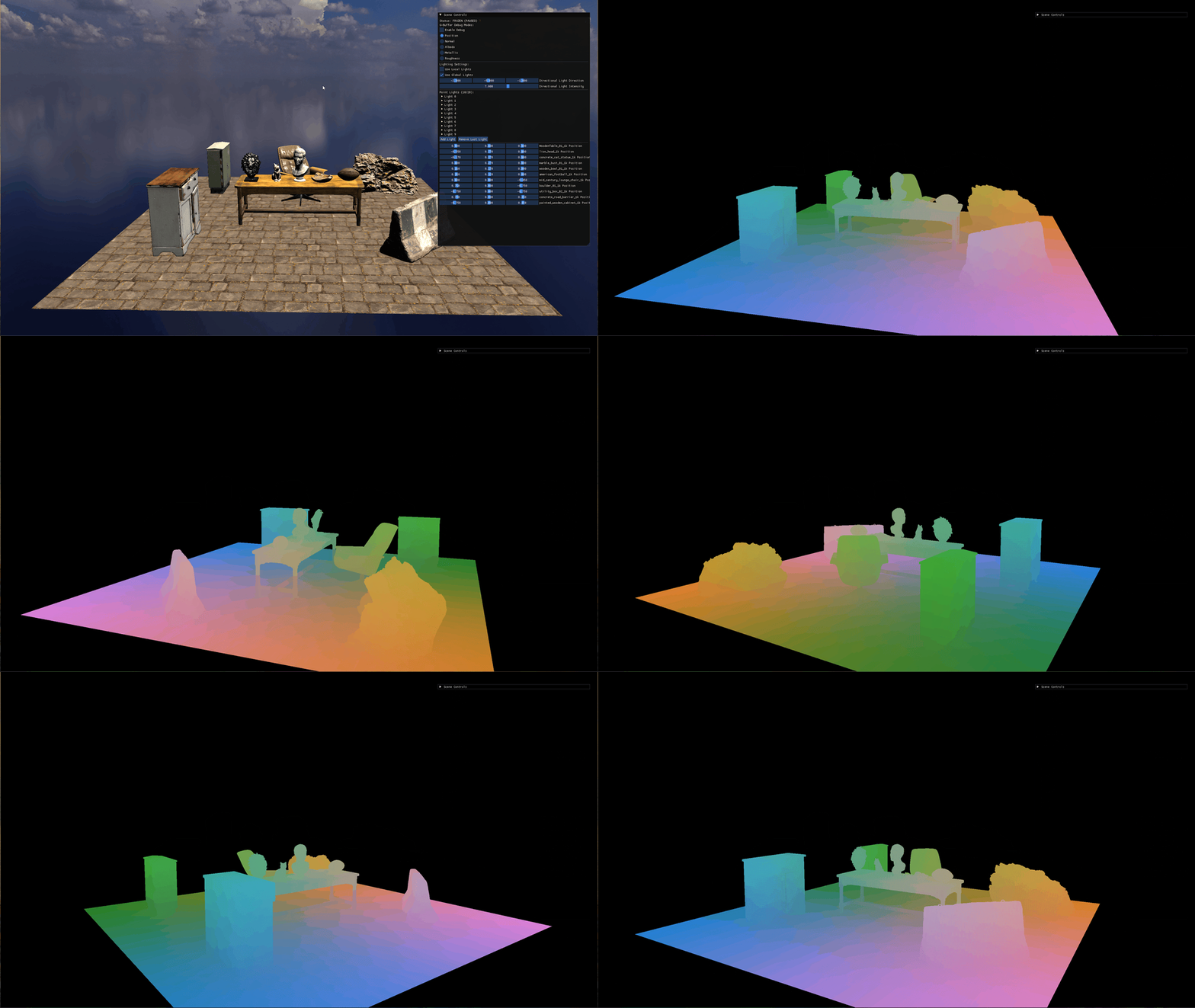
Observations
- Things towards the center and higher in the scene are whiter
- Things spread towards outside the center like barrier, boulder, cabinet take more combined colors from their respective components (x, y, z)
World-space position coordinates are mapped to RGB channels using logarithmic scaling:
- X axis: red channel
- Y axis: green channel
- Z axis: blue channel
Color mapping by axis
| X Axis | Y Axis | Z Axis | Resulting Color | RGB Values |
|---|---|---|---|---|
| + | + | + | White | (1.0, 1.0, 1.0) |
| + | + | − | Yellow | (1.0, 1.0, 0.0) |
| + | − | + | Magenta | (1.0, 0.0, 1.0) |
| + | − | − | Red | (1.0, 0.0, 0.0) |
| − | + | + | Cyan | (0.0, 1.0, 1.0) |
| − | + | − | Green | (0.0, 1.0, 0.0) |
| − | − | + | Blue | (0.0, 0.0, 1.0) |
| − | − | − | Black | (0.0, 0.0, 0.0) |
Normal maps
Tried out two types of normal map visualization:
One uses the normal abs(normal) to view the normal as absolute values in each of the channels (x- red, y-green, z-blue) to identify if the normal is mapped properly to their axes :
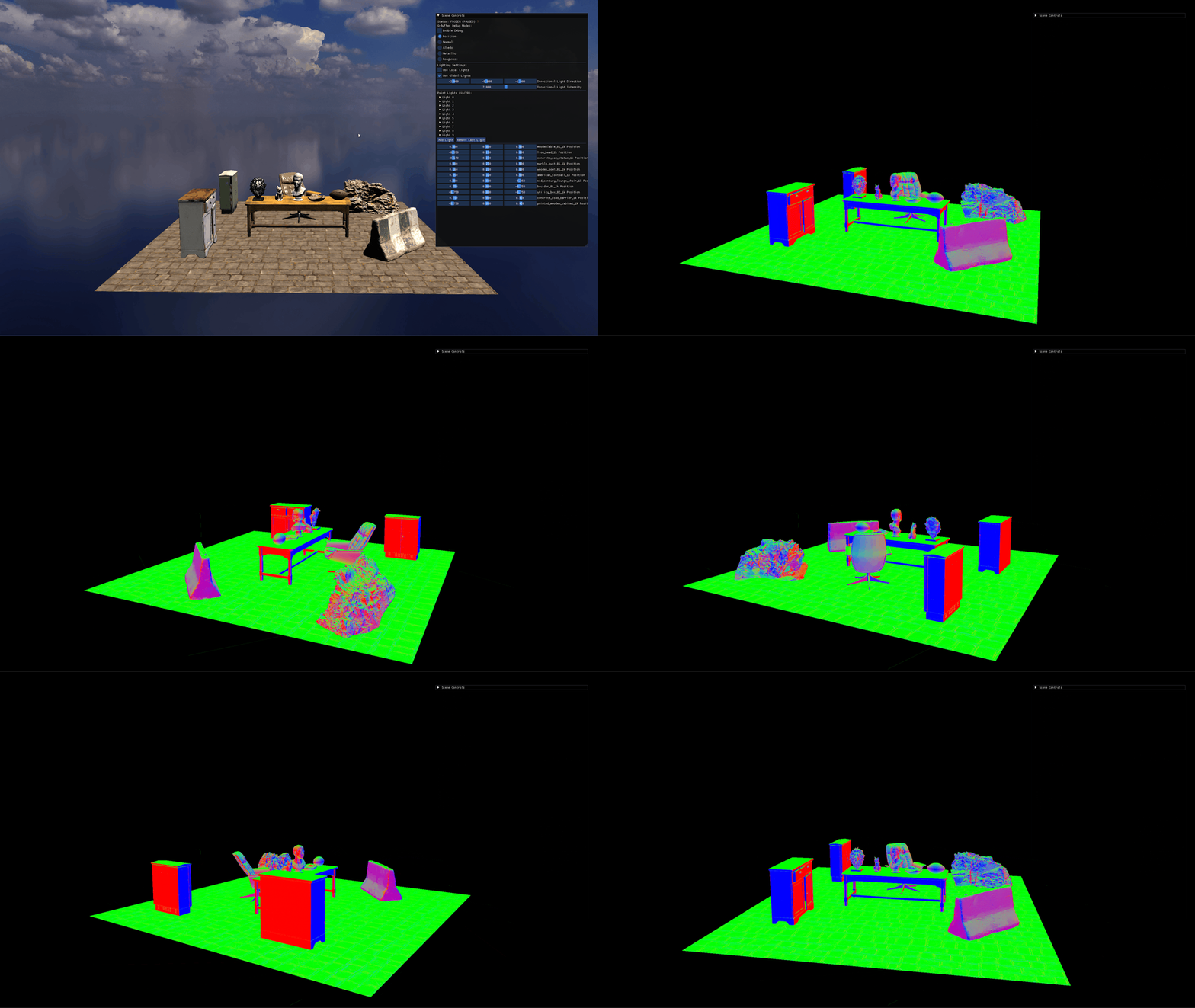
Observations
- Axis aligned model faces have the respective colors, like the front and back of the cabinet and utility box is red and the front/back of table is blue
- While the non-axis aligned components have a mixture of the component colors, like the barrier, boulder and chair.
Other allows to visualize that the direction of the normal is aligned properly within the axes [+ve vs -ve axis] (defferd_lighting_debug.frag :31-40
FragColor = vec4(normal * 0.5 + 0.5, 1.0);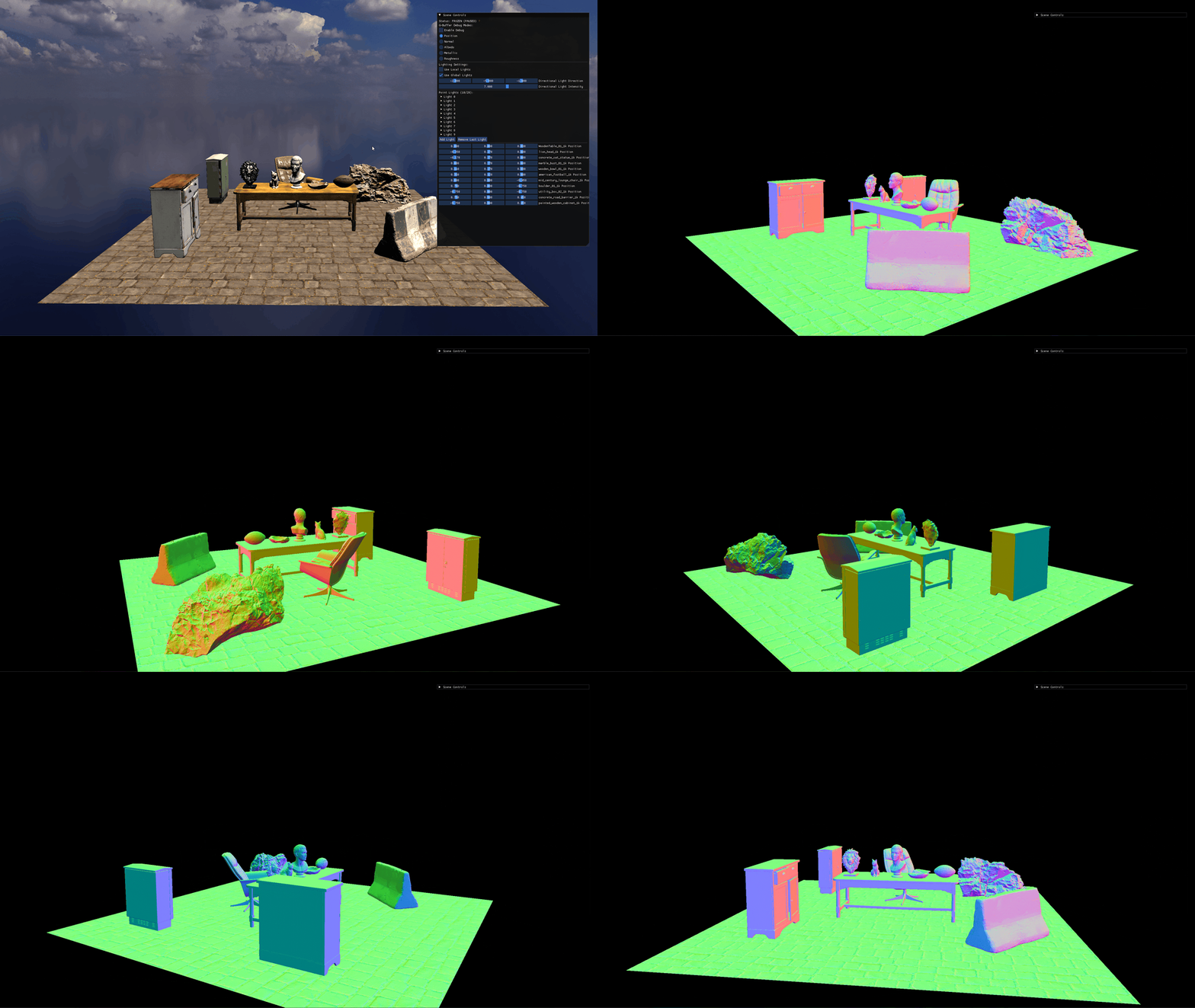
| Direction | Normal Vector | RGB Output | Visual Color |
|---|---|---|---|
| +X Axis | (1, 0, 0) | (1.0, 0.5, 0.5) | Light Red/Salmon |
| -X Axis | (-1, 0, 0) | (0.0, 0.5, 0.5) | Cyan |
| +Y Axis | (0, 1, 0) | (0.5, 1.0, 0.5) | Light Green |
| -Y Axis | (0, -1, 0) | (0.5, 0.0, 0.5) | Magenta/Purple |
| +Z Axis | (0, 0, 1) | (0.5, 0.5, 1.0) | Light Blue |
| -Z Axis | (0, 0, -1) | (0.5, 0.5, 0.0) | Yellow |
Observations
- The front of the cabinet and utility box is aligned with positive x so you see a salmon pink vs the back is aligned with negative x so you see more cyanish color
- While the front faces of the table, chair and the models on the table have more bluish tint to it, while the back of it is yellow
- And obviously the floor is perfectly aligned with the positive y-axis hence you see light green color.
Diffuse maps (albedo)
Visualizes the diffuse texture (or color) for all the models, applies the value directly without any extra computation (defferd_lighting_debug.frag :42-46)
 vec3 albedo = texture(gAlbedo, TexCoords).rgb;
 FragColor = vec4(albedo, 1.0);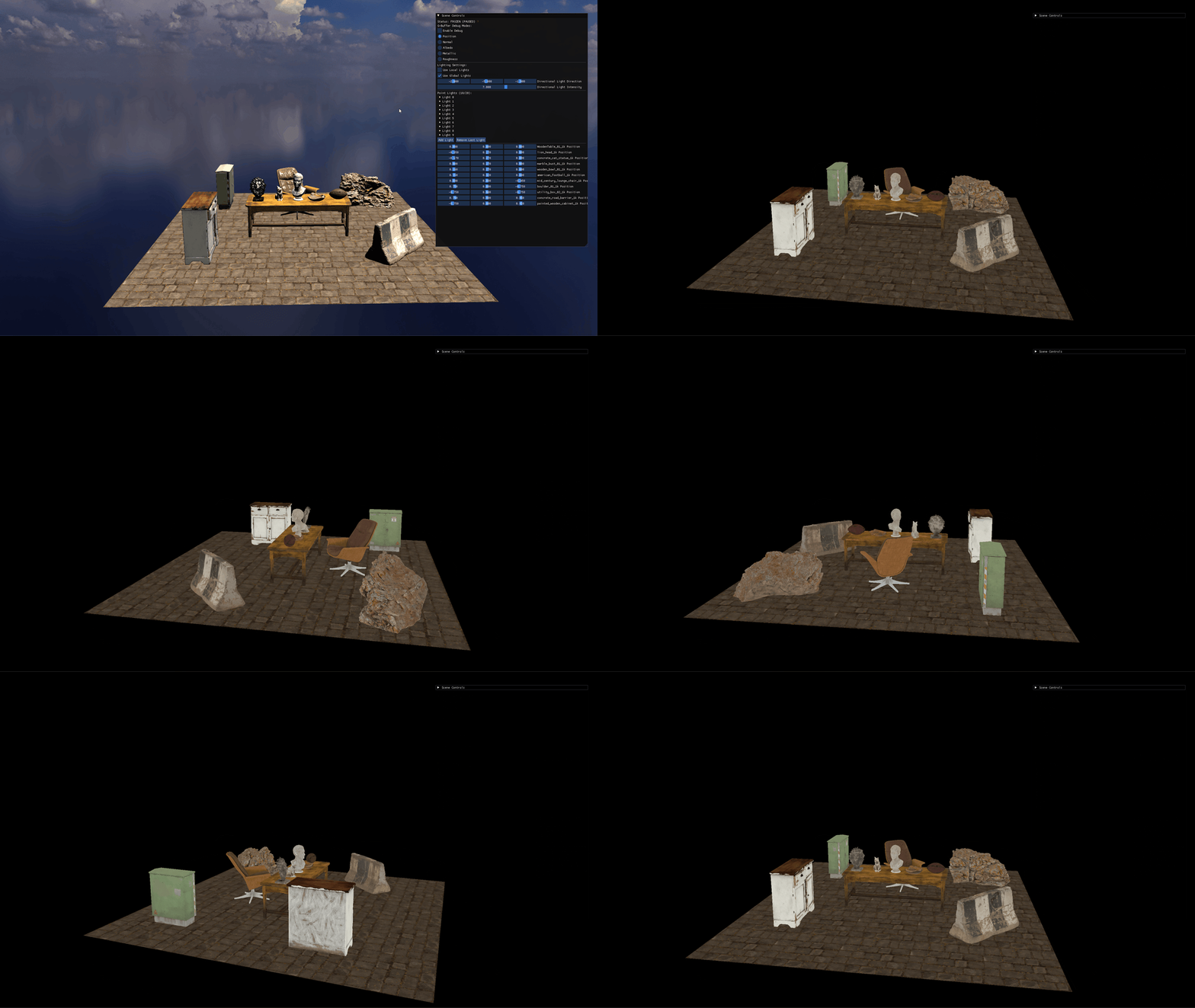
Observations
- We can validate if the diffuse textures or colors are applied properly to the models
- Some of the models may look a bit flat, like the boulder, since we are not doing any normal mapping
Metallic component
Visualizes the metallic components for all the models, applies the value directly without any extra computation (defferd_lighting_debug.frag :47-51)
float metallic = texture(gMetalRough, TexCoords).r;
FragColor = vec4(vec3(metallic), 1.0);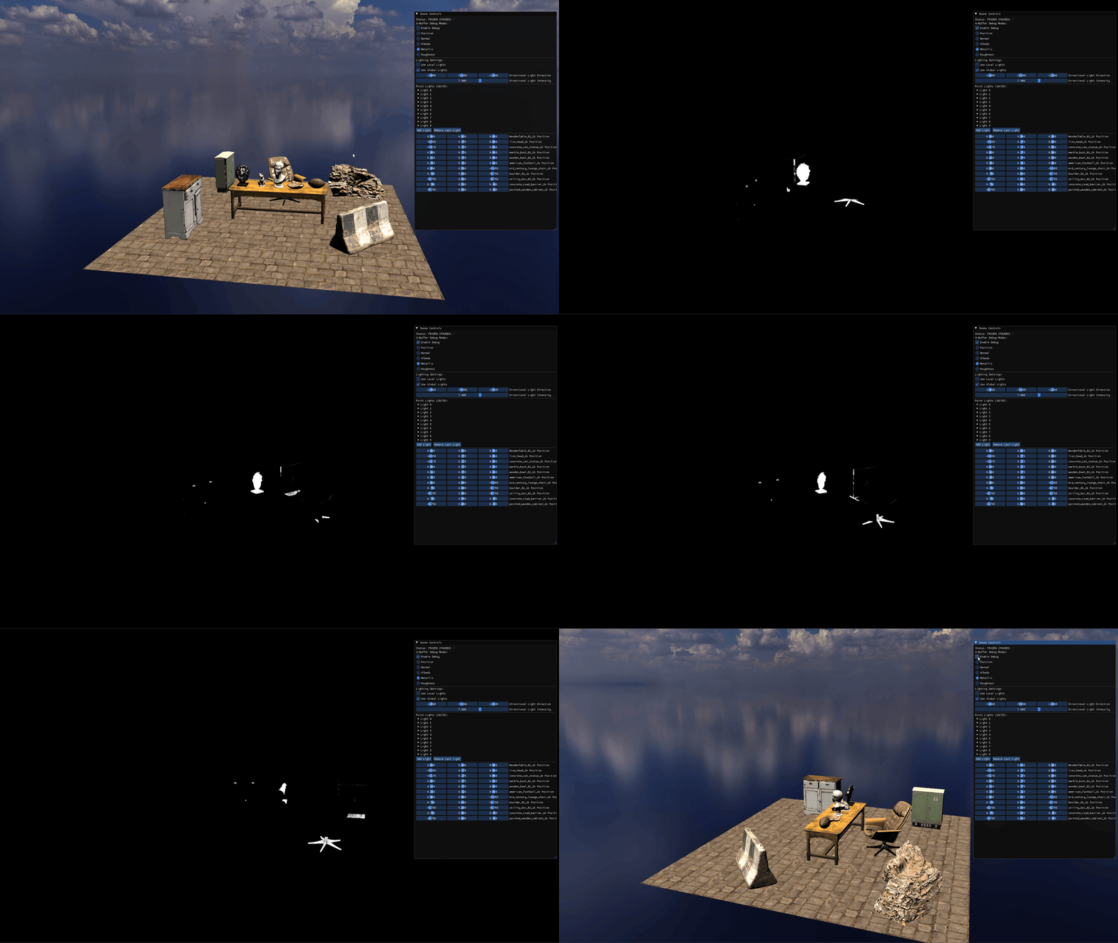
Observations
- We can validate if the metallic models or parts of the models are being mapped properly.
- In this case the Lion Head is made of brass, the base of the chair has some metal parts, similarly the base of the utility box and handles of the cabinet
Roughness component
Visualizes the roughness components for all the models, applies the value directly without any extra computation (defferd_lighting_debug.frag :52-56)
float roughness = texture(gMetalRough, TexCoords).g;
FragColor = vec4(vec3(roughness), 1.0);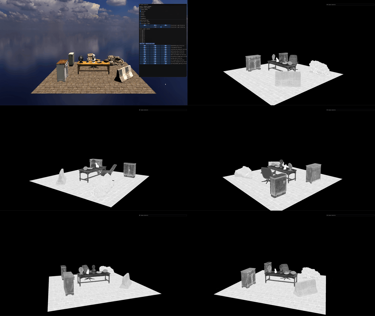
Observations
- We can validate the roughness aspects of different models
- We can see that the models which have less specular attributes (more rough), like the stone cat statue, the barrier and the boulder seem to have more white values
- The objects with more specular values (less rough), like the marble bust, lion head, chair seat, table surface are more towards the black regions of the grayscale mapping
Local lights visualization
Default light setup
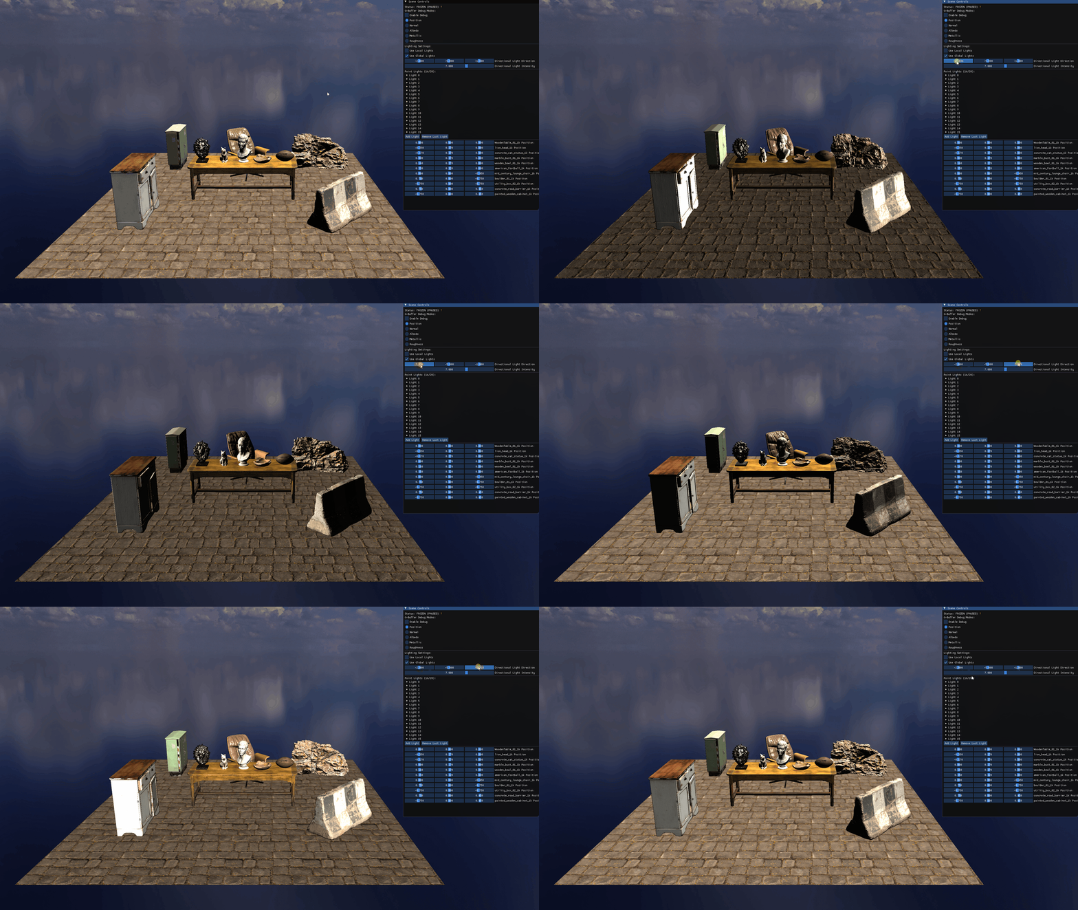
By default the scene has ten point lights positioned along the floor edges, five on each side (left and right), giving an ambient floor lighting effect with a warm orange color. The final scene has 20 lights (though it can go higher, haven’t tried to find the range where we start compromising frame rate).
The global directional light (sun) is positioned to shine from above at a slight angle from the X and Z axes. Its default intensity is high enough that the local floor lights are hard to see unless the global light is dimmed or disabled.
Default global + local lights
When viewing the scene with both global and local lights enabled:
Observations
- The global light dominates the overall scene illumination, making local light contributions subtle
- Local lights are visible primarily in areas not strongly illuminated by the global light
Local lights only (global light disabled)
When the global directional light is disabled or turned off, the local floor lights become the primary illumination source:
Observations
- The orange floor lights create distinct illumination pools across the scene
- Lighting is directional from the floor level, creating dramatic side-lighting effects
- Models positioned away from the light sources fall into shadow or receive minimal illumination
- The lighting is more spatially localized compared to the global light
Floor lighting effects
Normal map visibility with grazing illumination
When point lights graze across surfaces at shallow angles (such as floor-level lights illuminating the floor itself), surface normal mapping becomes much more visible:
Observations
- The floor’s normal map details are pronounced due to the grazing angle of the local lights
- Objects touching or near the floor (cabinets, utility box, boulder, barrier) are illuminated on their rear/side faces
- The front-facing surfaces of central scene objects receive minimal floor light contribution due to their orientation away from the low-angle light sources
- Mid-range and far-distance objects remain darker since the point lights have limited range
Specular reflections on lacquered surfaces
Models with low roughness (shiny, polished surfaces) show clear specular highlights from the local floor lights:
Observations
- The wooden table, with its lacquer finish (low roughness), shows distinct specular reflections from the floor lights
- The specular highlights move and shift as the viewpoint rotates, indicating proper PBR specular calculations
Metallic reflections and material contrast
Metallic objects reflect very differently from non-metallic materials:
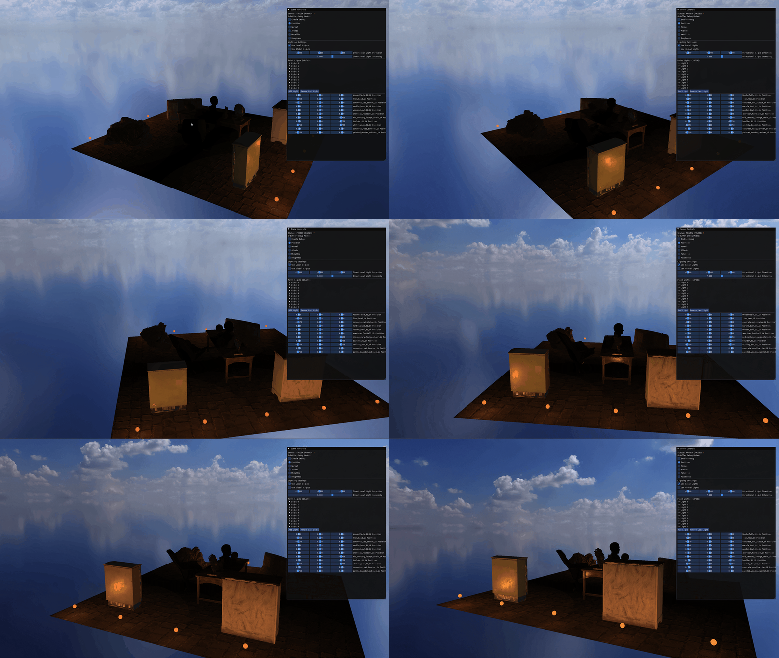
Observations
- The metal utility box displays sharp, pronounced specular highlights from the floor lights
- The wooden cabinet (non-metallic) near the utility box shows diffuse illumination without specular peaks
- The table surface still shows subtle specular reflections from its lacquered finish
Center models visualization
To show PBR material properties and light interaction, three more colored point lights illuminate the central scene models from different directions:
- Left light: gold
- Center light: red
- Right light: blue
Marble bust (polished dielectric)
The marble bust has a nearly white, polished porcelain surface with very low roughness, so it responds strongly to light color and direction:
Observations
- Left face (gold light): warm yellow illumination with sharp specular highlights
- Center region: transitions from gold to red as the light contribution shifts
- Right face (blue light): cool blue tones with sharp specular reflection
- Overall effect: the polished surface acts nearly like a mirror, showing the individual light colors without blending
- Specular component: dominant due to low roughness, which concentrates the highlights into points
Cat statue (matte stone surface)
The stone cat statue is a rough, matte dielectric with higher roughness, producing more diffuse lighting interactions:
Observations
- Left face (gold light): warm yellow diffuse illumination, less distinct than the marble bust
- Right face: a blend of red and blue illumination with softer color transitions
- Surface appearance: less shiny than the marble bust; specular highlights are subdued
- Color mixing: more visible color blending at the transition regions, since the surface roughness diffuses the light
- Reduced range effect: when light range is reduced, darker regions appear on back faces, showing the spatial light falloff
- Roughness visibility: the rough texture becomes more pronounced with grazing light angles
Lion head (polished metal, brass)
The brass lion head is a low-roughness metallic object, so it shows the metallic side of the BRDF:
Observations
- Left region: yellow illumination with strong metallic specular reflection
- Right region: a mixture of red and blue as the viewing angle captures multiple light sources
- Metallic property: the surface has higher reflectance at all angles
- Rotational view: as the model is rotated, specular highlights appear in different regions based on view angle and light geometry
- Back surface: minor traces of all three colored lights
- Color saturation: metallic surfaces show colors slightly modified by the brass base color, not the pure light colors
Wooden bowl and football (rough non-metallic)
Both objects have higher roughness and non-metallic (dielectric) properties:
Observations
- Roughness characteristic: high diffuse scattering with minimal specular component
- Lighting sources: mostly lit by the elevated gold light, with little contribution from the side-positioned red and blue lights
- Edge lighting: the wooden bowl’s edges (closest to the red side light) pick up additional red color saturation
- Range effect: when light range is reduced, the illumination becomes more localized, which shows the distance-based attenuation
- Surface texture: the rough surfaces hide small-scale specularity, so the normal map details dominate instead
- Table interaction: specular reflections from the lacquered table surface are visible beneath these objects
Leather lounge chair (medium roughness metal + leather)
The lounge chair combines leather seat surfaces with metallic base components:
Observations
- Leather seat: diffuse yellow illumination from the overhead gold light, with visible normal map detail
- Back surface: green illumination from the rear-positioned light, with softer color transitions due to the leather roughness
- Seat texture: the low-angle lighting picks out the bump details, so the micro-geometry is prominent
- Metal base: the support structure shows the sharp specular highlights of a low-roughness metallic surface
- Boulder interaction: the boulder to the side is also faintly lit by the green light source, showing how the light spreads to nearby geometry
- Material contrast: the leather (diffuse, textured) and the metal base (specular, smooth) read as clearly different materials
Light color blending (multi-light interaction)
The boulder demonstrates color mixing when illuminated by multiple light sources:
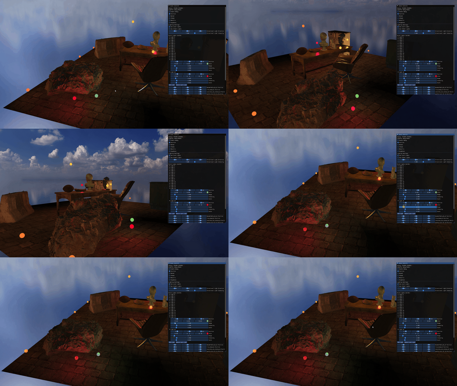
Observations
- Color mixing mechanism: where the red and green lights contribute equally, the surface appears yellow (additive color mixing)
- Spatial separation: front-facing surfaces show an orange tint from the distant floor lights
- Rear surfaces: a blend of red and green contributions, with the intensity of the blend changing as light range is adjusted
- Range effect: reducing individual light ranges isolates their contributions visually, showing how each light affects the surface color independently
- Rotation behavior: as the boulder is rotated, the relative contribution of each light changes, which confirms that the light direction calculations in the PBR model are right
- Falloff characteristic: the smooth falloff of light color contribution validates the distance-based attenuation (inverse-square law) implementation
File structure
src/
├── shaders/
│   ├── gbuffer.vert                 # G-Buffer vertex shader
│   ├── gbuffer.frag                 # G-Buffer fragment shader
│   ├── deferred_lighting.vert       # Deferred lighting vertex shader
│   ├── deferred_lighting.frag       # PBR Cook-Torrance BRDF lighting shader
│   └── deferred_lighting_debug.frag # G-Buffer debug visualization shader
│
├── include/
│   ├── Camera.h                     # Camera class with view/projection matrices
│   ├── Shader.h                     # Shader compilation and uniform management
│   ├── Model.h                      # Model loading and management
│   ├── Floor.h                      # Floor mesh generation
│   ├── Scene.h                      # Scene management and rendering
│   ├── PointLight.h                 # Point light structure and management
│   ├── FrameBuffer.h                # Framebuffer objects (G-Buffer, lighting FBO)
│   └── Texture.h                    # Texture loading and management
│
├── Model.cpp
├── Mesh.cpp
├── Scene.cpp
├── PointLight.cpp
├── FrameBuffer.cpp
├── Texture.cpp
└── Main.cpp                         # Application entry point and render loop